By Nazakat Ali – Watt Vission
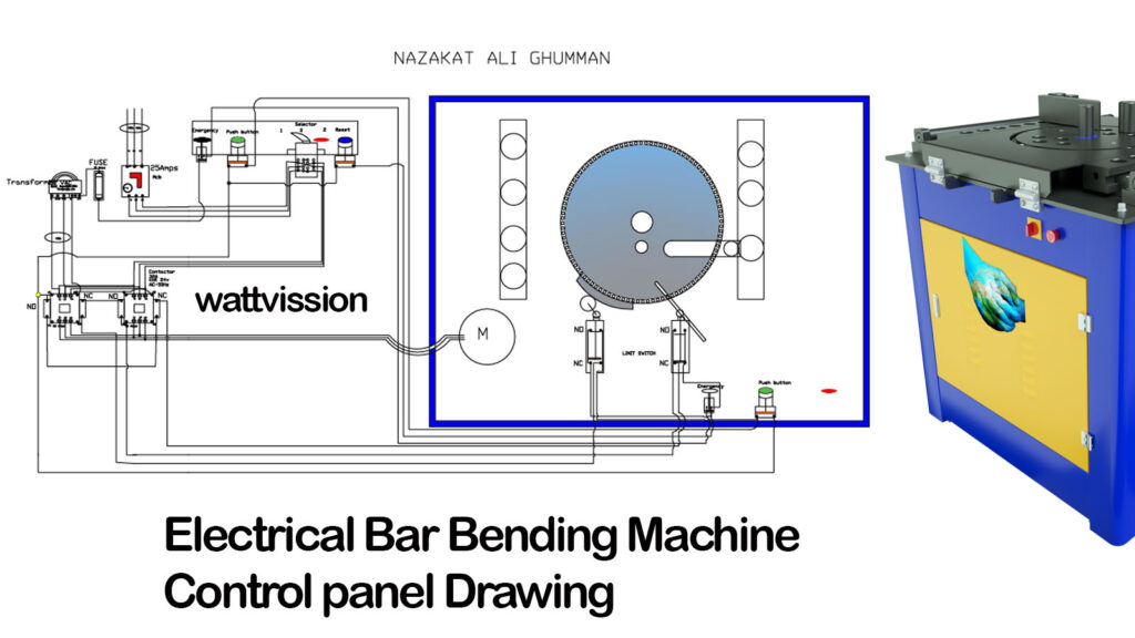
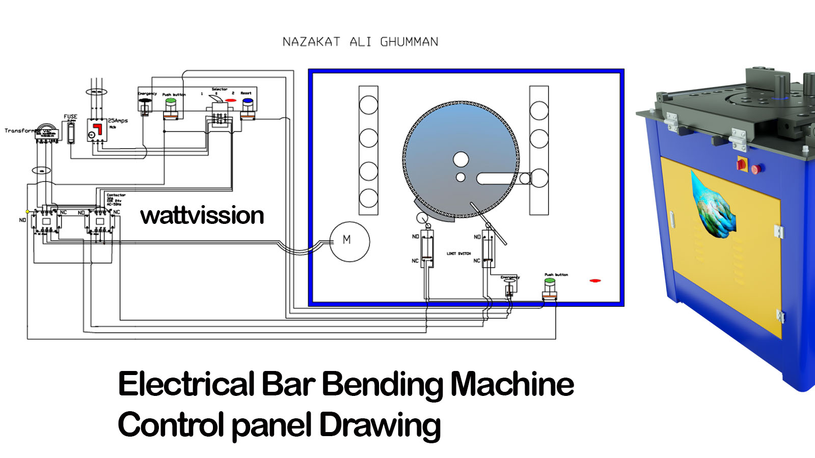
This guide outlines the wiring setup for a Bar Bending Machine control panel, detailing the connections from the main power supply through various components, including limit switches, push buttons, and contactors.
Wiring Components and Connections:
- Main Power Supply (3-Phase):
- The 3-phase wire connects to the MPCB (Motor Protection Circuit Breaker). The MPCB safeguards the machine from overloads and short circuits.
- Selector Switch:
- Wiring proceeds from the MPCB to a 2-way selector switch. This switch allows the operator to select the motor’s running direction (forward or reverse).
- Ensure the wiring enables the desired direction changes.
- Contactors:
- The output from the selector switch leads to two contactors—one for forward operation and another for reverse.
- Connect the center wire of one contactor to either the left or right terminal of the other contactor, allowing seamless transitions between operational modes.
- Transformer Connections:
- Each contactor connects via two wires to a transformer, which can operate on either 380V or 220V input.
- The transformer provides a 24V AC output, powering the control circuit.
- Coil Connections:
- One wire from the transformer goes to the coil of the contactor (24V connection), energizing the contactor when activated.
- The second wire connects to a 10A MCB fuse for overcurrent protection.
- Emergency Stop and Push Button:
- One wire from the emergency stop switch connects to the NC (Normally Closed) terminal of a limit switch. The second wire from this limit switch connects to the push button switch.
- When the push button is pressed, it sends a signal to the contactor coil (A2 terminal) and connects to the other limit switch.
- Contactor Operation:
- As the push button is pressed, the contactor is energized, allowing it to hold and work continuously.
- To stop the contactor, the current from the first limit switch (using its NC terminal) is redirected to the NC terminal of the contactor, thus energizing the coil.
- Limit Switch Functionality:
- The first limit switch allows current to flow through its upper terminal directly to the NC terminal of the first contactor and then to the other terminal of the coil, enabling the contactor to maintain its hold.
- When the bending machine’s circle reaches the second limit switch, it stops the current flow, deactivating the machine.
- Motor Connection:
- The main wire from the contactor connects to the motor, ensuring proper operation based on the selected contactor.
- The machine stops automatically when the bending process reaches the second limit switch.
Practical Implementation:
- Follow this wiring diagram carefully for accurate connections.
- For visual guidance, practical videos are available on the Watt Vission YouTube channel. Visit Watt Vission for tutorials and further information.
Conclusion
This comprehensive wiring guide ensures safe and effective operation of the Bar Bending Machine. Each component plays a vital role in the machine’s overall functionality, allowing for precise control during bending operations.
Brought to you by Nazakat Ali and Watt Vission, your reliable source for electrical tutorials and solutions.

Well job done
Very explained and informative
Thank you so much! 😊